
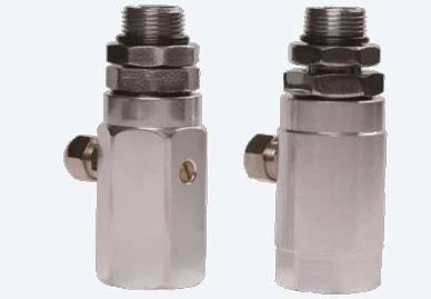
محول الفاصل
محول فصل البخار عن السائل يُركّب بين الفوهة والخرطوم. ونسخة اختيارية مع ضبط نسبة السائل إلى البخار.
| سن مدخل الزيت | G3/4" |
| سن مخرج الزيت | M34 × 1.5 |
| سن مجرى الهواء | G1/4" |
| Options | مع تعديل نسبة السائل/البخار أو بدونه |
طقم تعديل Stage II كامل بمساعدة التفريغ: مضخات VR وفوهات التوازن وخراطيم استعادة الأبخرة وكل الوصلات اللازمة لتمديد الموزع لاستعادة الأبخرة.
The vacuum source that pulls vapor back from the vehicle fill pipe. Mounted inside the dispenser — DT-VR1 carries one pump head, DT-VR2 carries two, and DT-NP80 is the low-voltage NP type with its own controller.
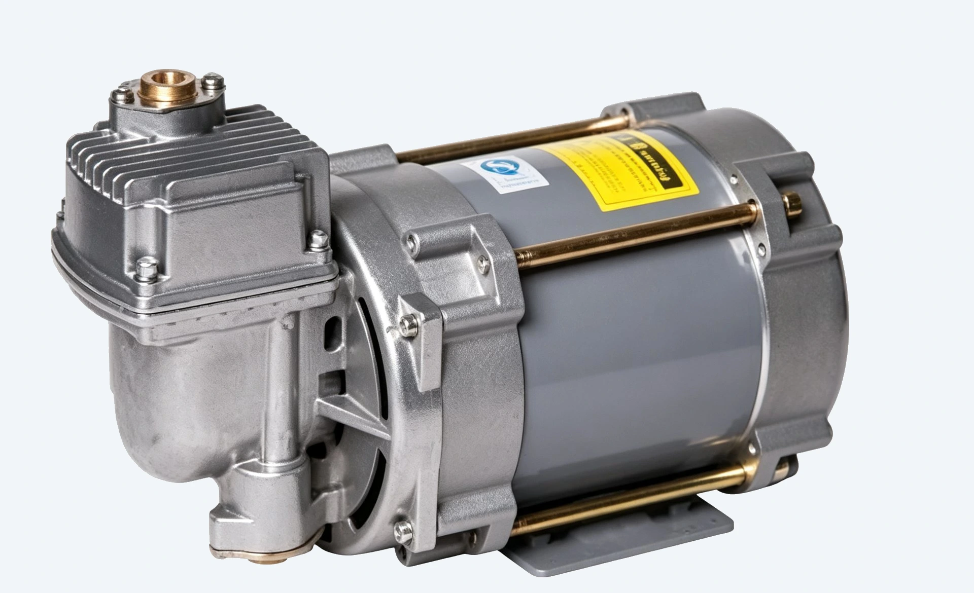
رأس مضخة واحد. يُركَّب داخل موزع الوقود ويخدم فوهة واحدة.
| Voltage | 220 V / 380 V |
| Heads | 1 |
| Nozzle capacity | One nozzle |
| Mounting | Inside dispenser |
مواصفات DT-VR1 →
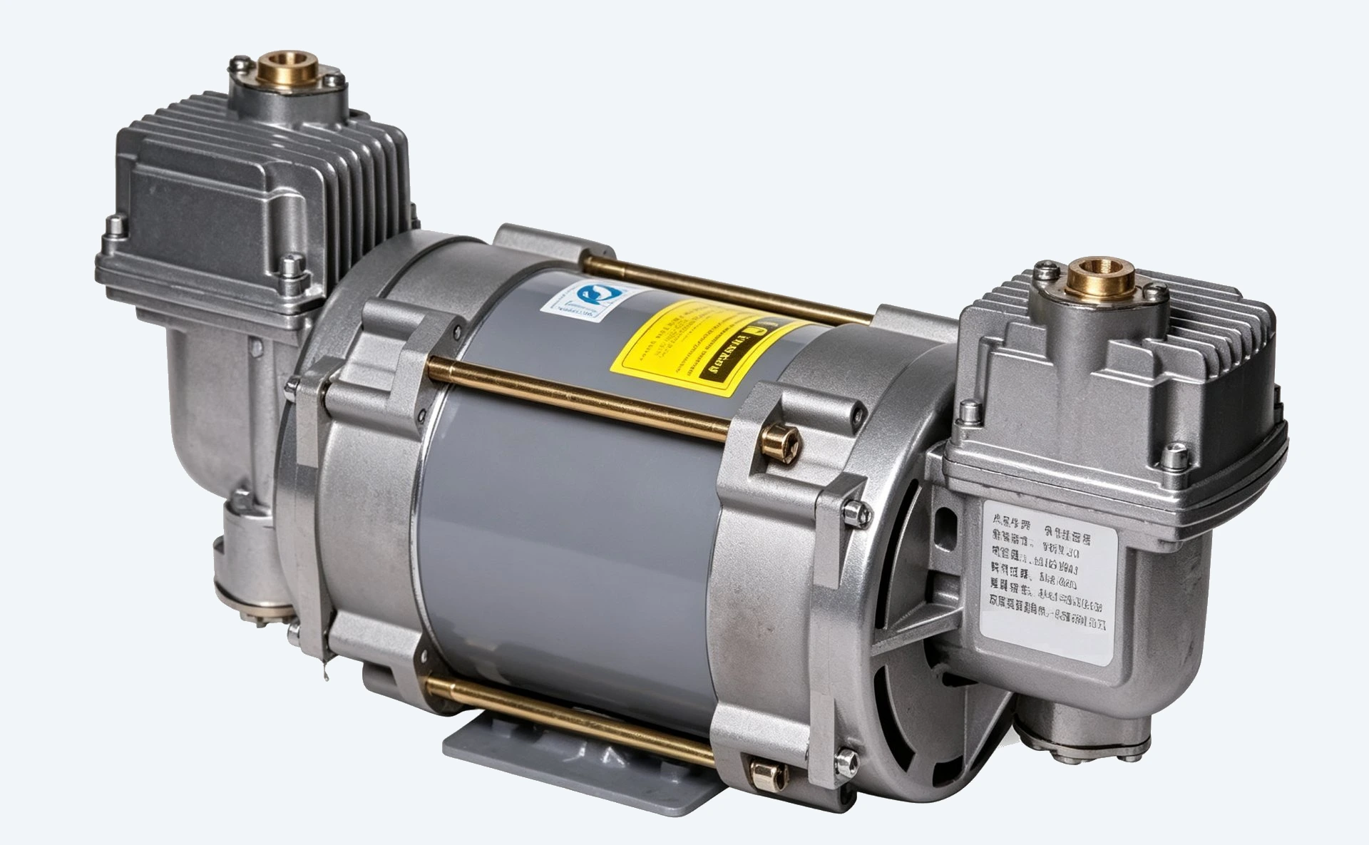
رأسان مضخة. يُركَّبان داخل موزع الوقود ويشتركان في فوهتين.
| Voltage | 220 V / 380 V |
| Heads | 2 |
| Nozzle capacity | Two nozzles |
| Mounting | Inside dispenser |
مواصفات DT-VR2 →
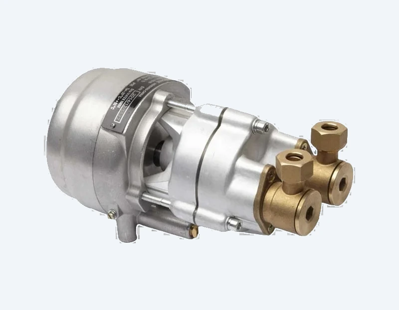
مضخة تفريغ من نوع NP مزودة بوحدة تحكم خاصة، وحدة واحدة لكل فوهة. Ex db IIA T3 Gb.
| Type | NP pump with controller |
| Voltage | 36 V DC |
| Nozzle capacity | One nozzle |
| Mounting | Inside dispenser |
مواصفات DT-NP80 →
الجزء الجوهري في الطقم. تلتقط فوهة التوازن الأبخرة عند نقطة التعبئة، وينقل الخرطوم المحوري الوقود إلى الخارج والأبخرة إلى الداخل في مجموعة واحدة.
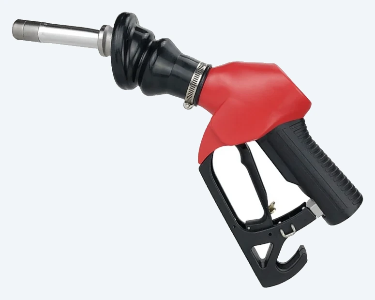
فوهة توازن من نوع ZVA بمسار إعادة الأبخرة مدمج لتوزيع مع استعادة الأبخرة Stage II.
المواصفات الكاملة →
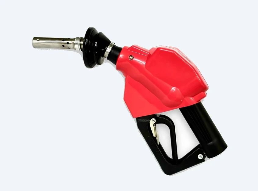
فوهة توازن من نوع OPW بمسار إعادة الأبخرة. اختر ZVA أو OPW حسب تفضيل المحطة.
المواصفات الكاملة →
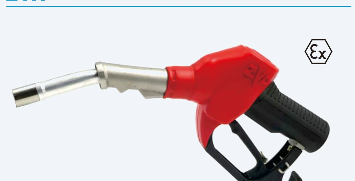
فوهة توازن من نوع ZVA بمسار إعادة الأبخرة مدمج لتوزيع مع استعادة الأبخرة Stage II.
المواصفات الكاملة →
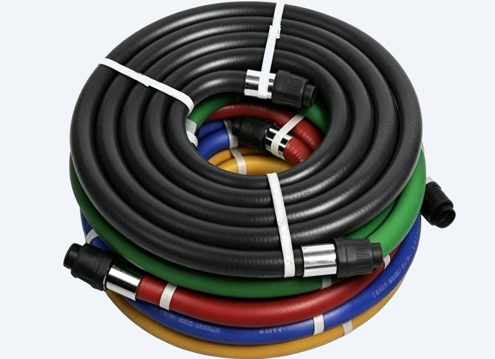
خرطوم استعادة أبخرة مرن يُورَّد بغلاف خارجي أسود أو ملوّن. خرطوم واحد لكل فوهة.
المواصفات الكاملة →
كل ما بين الفوهة وخط أبخرة الموزع — حماية القطع، والفصل، وأنابيب النحاس أو الألومنيوم التي تُغلق الحلقة.

ينفصل صمام القطع في الخرطوم عند قوة سحب مصممة مسبقاً لحماية موزع الوقود والأنابيب، ثم يُغلق تلقائياً.
| Thread | M34 × 1.5 |
| Body material | Aluminum |
| Seal material | Viton |
| Quantity rule | One unit per nozzle |
مواصفات قاطع الأمان DT VR →
محول فصل البخار عن السائل يُركّب بين الفوهة والخرطوم. ونسخة اختيارية مع ضبط نسبة السائل إلى البخار.
| سن مدخل الزيت | G3/4" |
| سن مخرج الزيت | M34 × 1.5 |
| سن مجرى الهواء | G1/4" |
| Options | مع تعديل نسبة السائل/البخار أو بدونه |
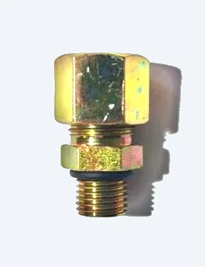
وصلة نحاسية بين خرطوم VR وخط الأبخرة في الموزع.
| Material | Brass |
| Function | وصّل الخرطوم بخط الأبخرة في الموزع |
| قاعدة الكمية | واحد لكل نقطة توصيل |
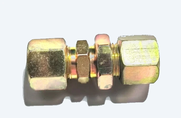
وصلة مستقيمة عبر الحاجز / للتثبيت لتمرير أنابيب النحاس عبر لوحة الموزع.
| Type | Straight / high-mount |
| Application | مسار أنابيب النحاس |
| Note | اختياري حسب تعديل الموزع |
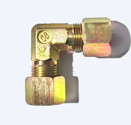
وصلة كوع بزاوية قائمة لتغيير اتجاه مسار الأنبوب النحاسي.
| Type | 90° elbow |
| Application | مسار أنابيب النحاس |
| Note | اختياري حسب تعديل الموزع |
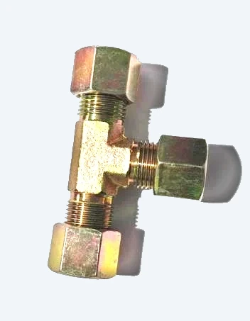
وصلة تي ثلاثية لتفرع الأنبوب النحاسي داخل الموزع أو حوله.
| Type | Three-way / tee |
| Application | مسار أنابيب النحاس |
| Note | اختياري حسب تعديل الموزع |
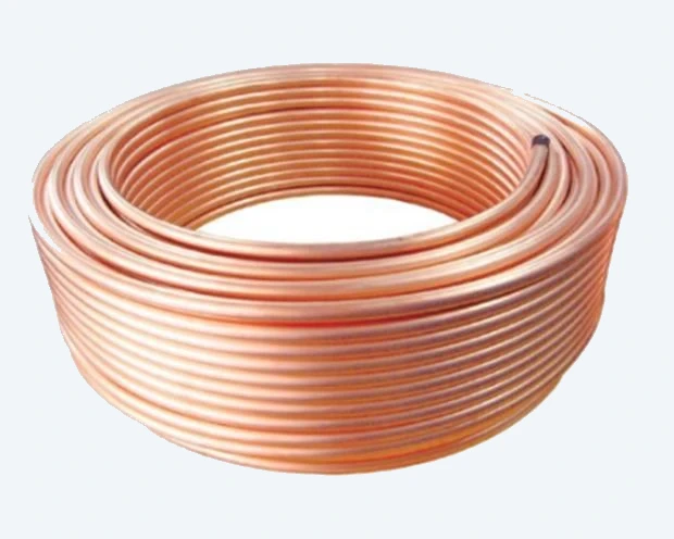
أنابيب نحاس تُباع بالمتر. يُحدَّد الطول النهائي وفق تخطيط الموقع وموضع موزع الوقود.
| Material | Copper |
| وحدة البيع | بالمتر |
| Note | الكمية تعتمد على الموقع |
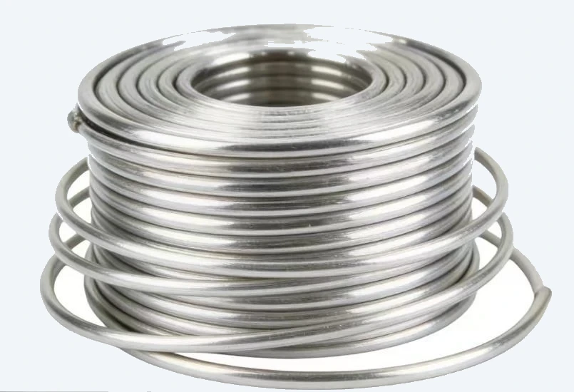
أنابيب ألمنيوم تُباع بالمتر. تُستخدم كبديل خفيف للنحاس حيث يسمح التخطيط بذلك.
| Material | Aluminum |
| وحدة البيع | بالمتر |
| Note | الكمية تعتمد على الموقع |
البنود أعلاه مستخرجة من عرض سعر طقم التعديل لاستعادة الأبخرة Stage II. الكميات الخاصة بأنابيب النحاس وأنابيب الألمنيوم والوصلات الصغيرة تقديرات مرجعية؛ ويجب تأكيد الاستهلاك النهائي بعد معاينة الموقع.
معظم أعمال التعديل تنتهي عند إحدى قائمتي المواد هاتين. اختر الحزمة بحسب عدد الفوهات لديك، ثم أرسلها إلينا للحصول على سعر نهائي.
فوهة وقود واحدة · مضخة تفريغ برأس واحد
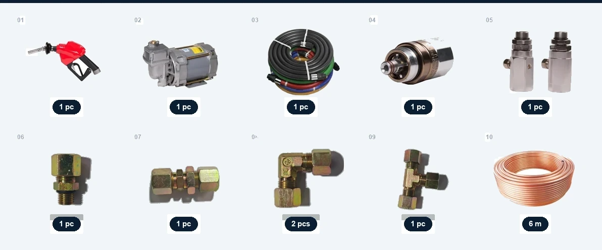
إجمالي الحزمة A — عند الطلب
FOB Ningbo, per package
فوهتا وقود · مضخة مشتركة برأسين
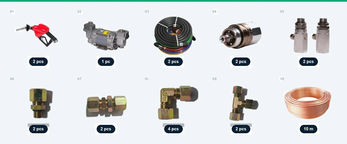
إجمالي الحزمة B — عند الطلب
FOB Ningbo, per package
مضخة مشتركة واحدة، لا اثنتان. Package B covers twice the nozzles for less than two Package A kits — the dual-head pump is where the saving sits. Ask us to quote both and compare the per-nozzle figure yourself.
Both packages are quoted per kit. Budgeting for a whole station? Multiply the package by your actual nozzle count — we will confirm the mix after a site inspection, and consolidate everything into one container.
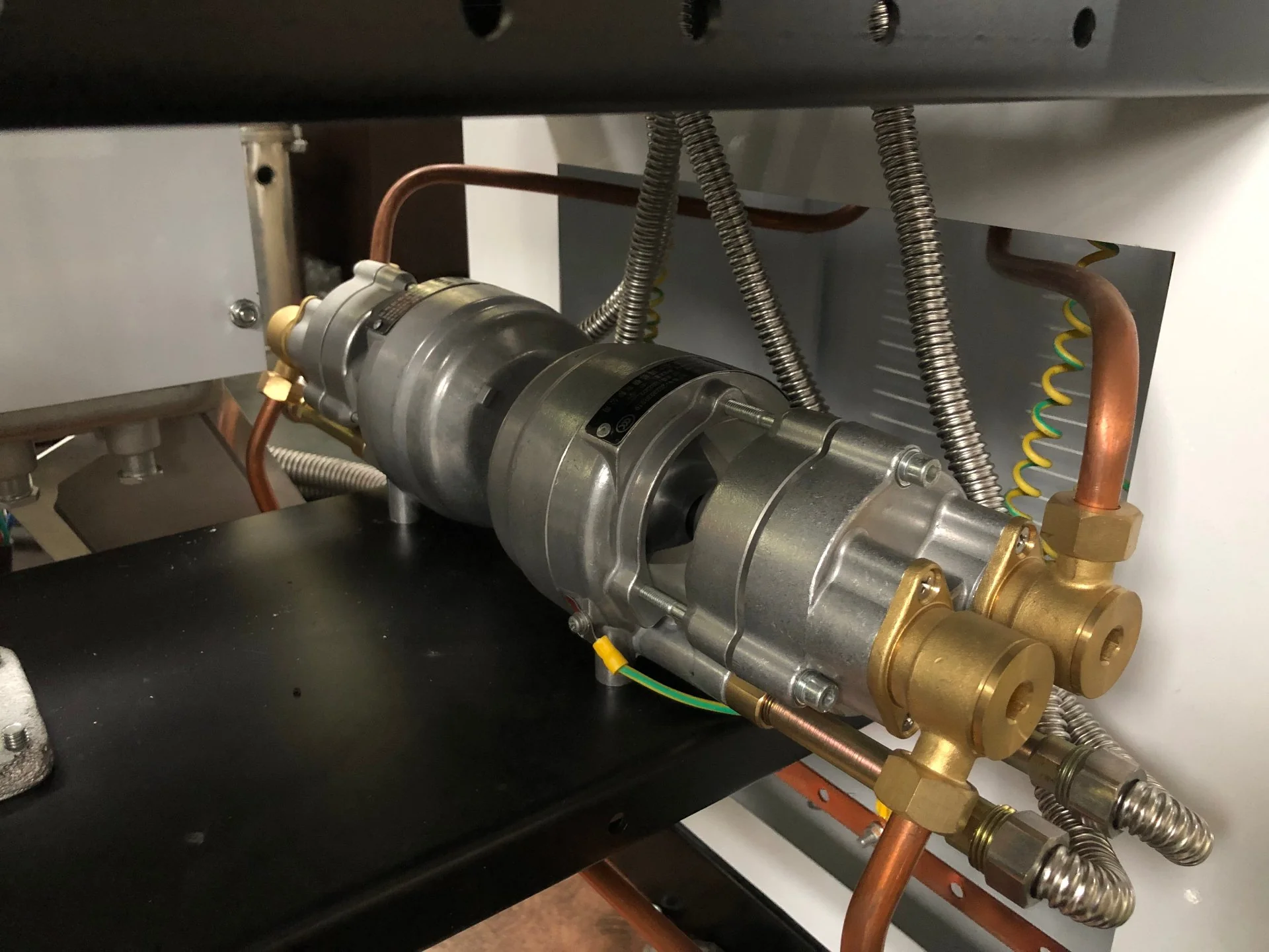
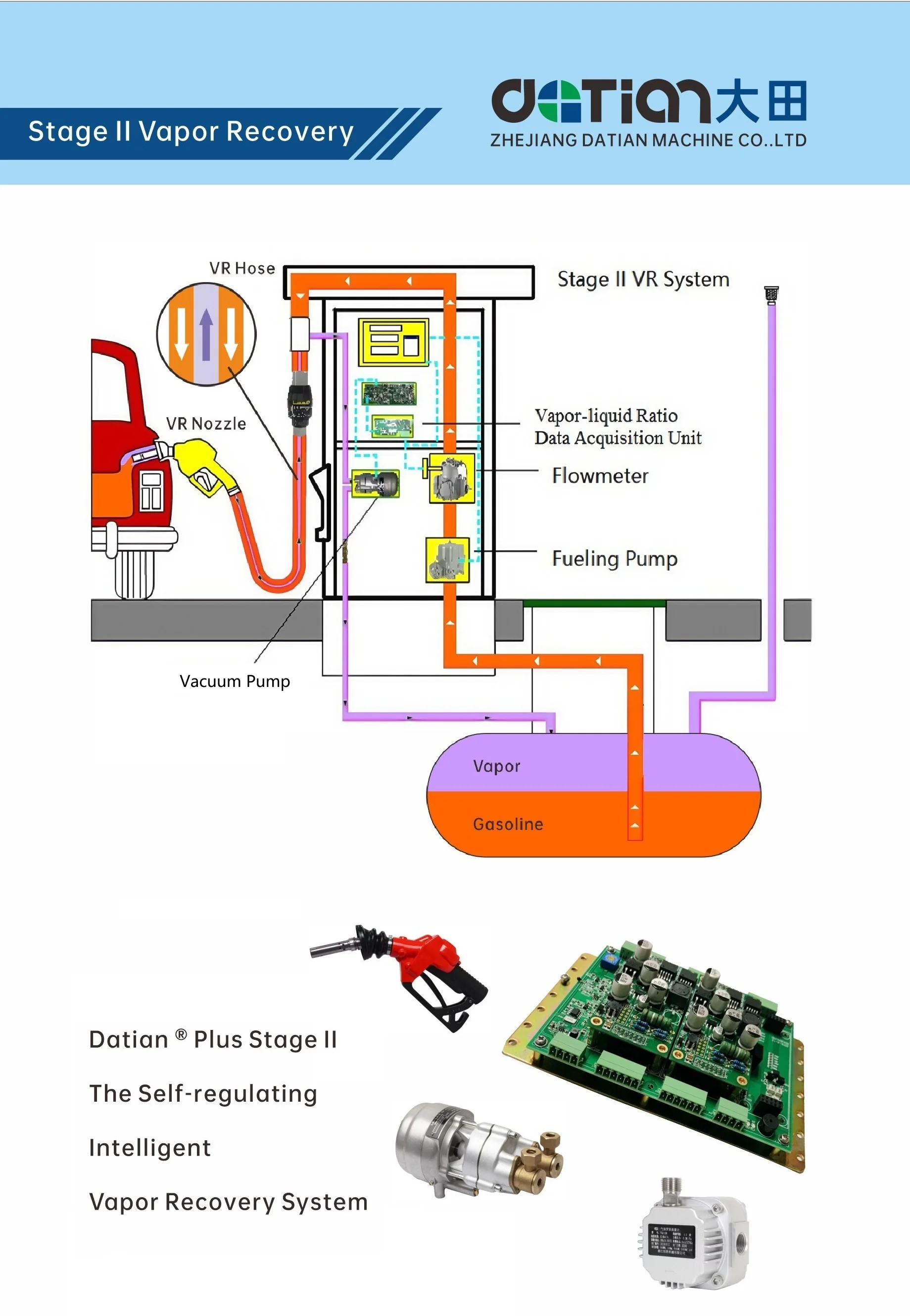
Vapor is pulled from the vehicle tank through the VR nozzle and hose, passes the vacuum pump inside the dispenser, and returns into the underground storage tank, while the flowmeter and vapor-liquid ratio unit keep the ratio in check. Every part in this loop is covered by sections 01–04 above; the photos show the hardware in our workshop.
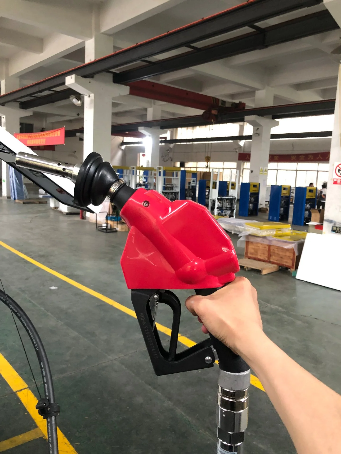
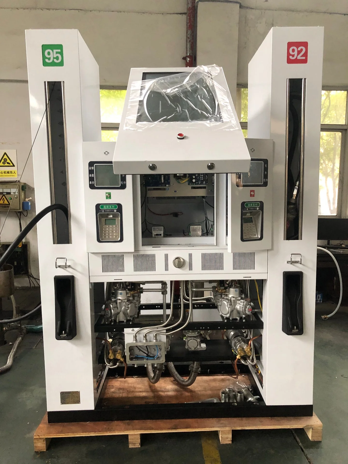
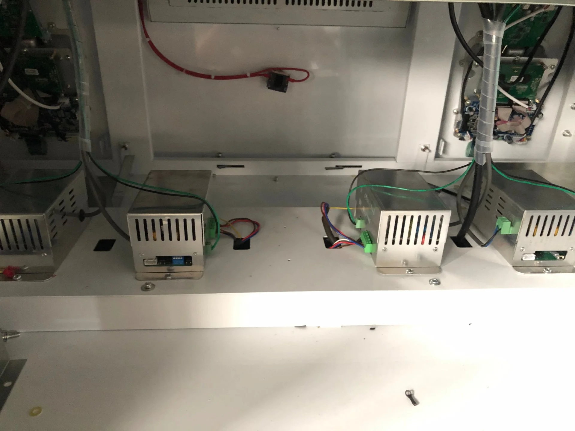
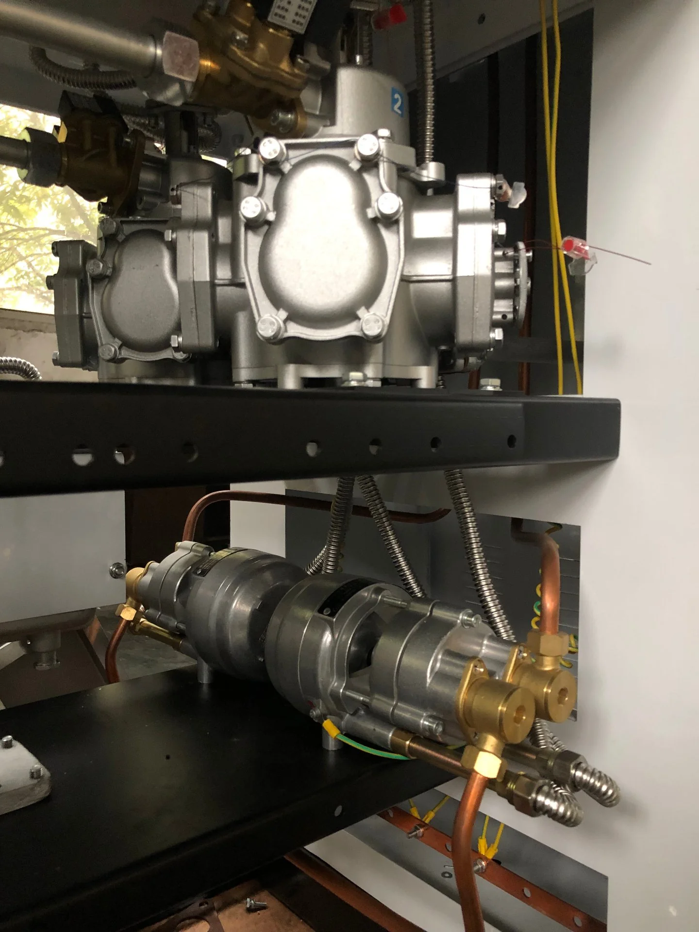
The five questions we are asked most often when a forecourt retrofits for Stage II vapor recovery.
Count the nozzles that will run vapor recovery. One nozzle per dispenser side takes Package A — one single-head pump, 220 V or 380 V. Two nozzles sharing one housing take Package B, where a single dual-head pump serves both, so the second nozzle costs far less than a second Package A kit.
The kit is built around your dispenser, not the other way round. The vacuum pump mounts inside the dispenser cabinet, the nozzle is available in ZVA or OPW type, the breakaway valve couples on an M34 × 1.5 thread, and the separation adaptor takes a G3/4" oil inlet with a G1/4" vapor port. Send us the dispenser make and model and we will confirm the thread set and the pump position before you order.
DT-VR1 carries one pump head and DT-VR2 carries two; both mount inside the dispenser and run on 220 V or 380 V. DT-NP80 is the NP type with its own controller, 36 V DC, one unit per nozzle, marked Ex db IIA T3 Gb.
The breakaway valve separates under its designed pull force and closes automatically, protecting the dispenser and the pipework. One unit per fuel nozzle; aluminium body with Viton seals.
Both packages are quoted per kit on an FOB Ningbo basis, and the figure is confirmed after a site inspection. Copper pipe is cut to your actual run (6 m in Package A, 10 m in Package B), while pump voltage, nozzle brand and vapor-liquid ratio adjustment are order options. Retrofitting a whole station? Multiply the package by your nozzle count — everything ships consolidated in one container.
Still unsure which parts you need? Send us the dispenser model and a photo of the nozzle boot area — we will come back with a bill of materials.
Tell us your dispenser model, nozzle count and local vapor recovery regulation — we will spec the full kit and quote within 24 hours.
Request a Kit Quote Stage III Green Guard