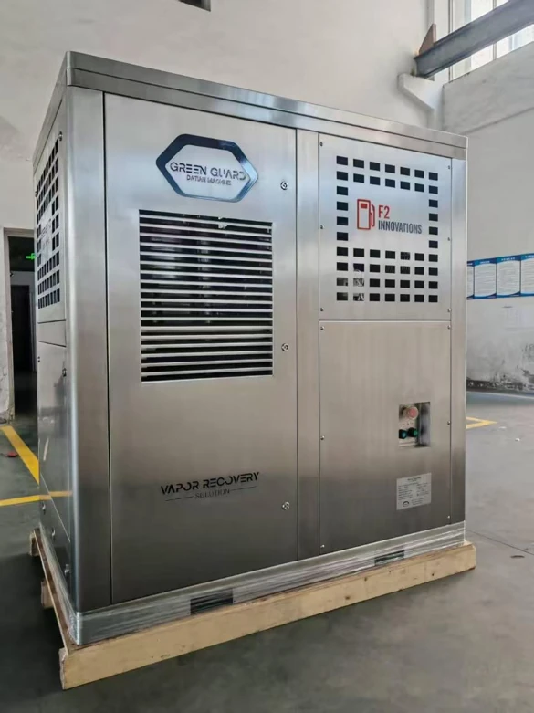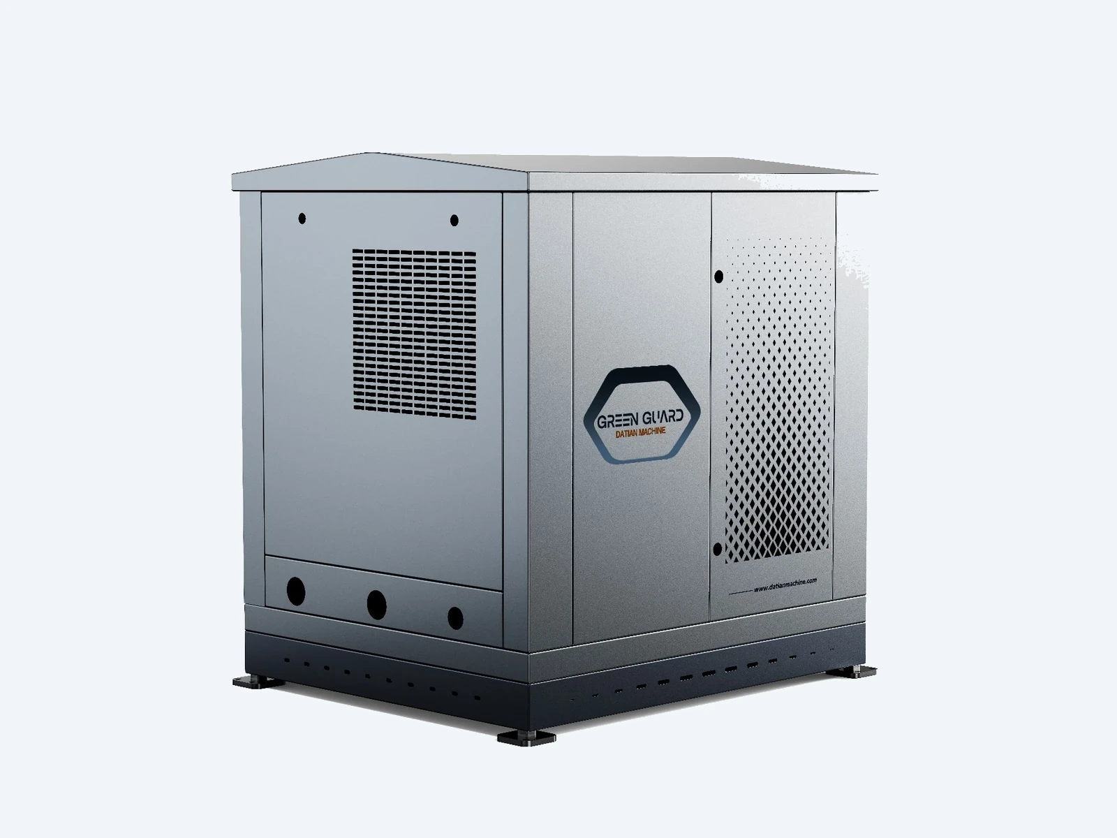
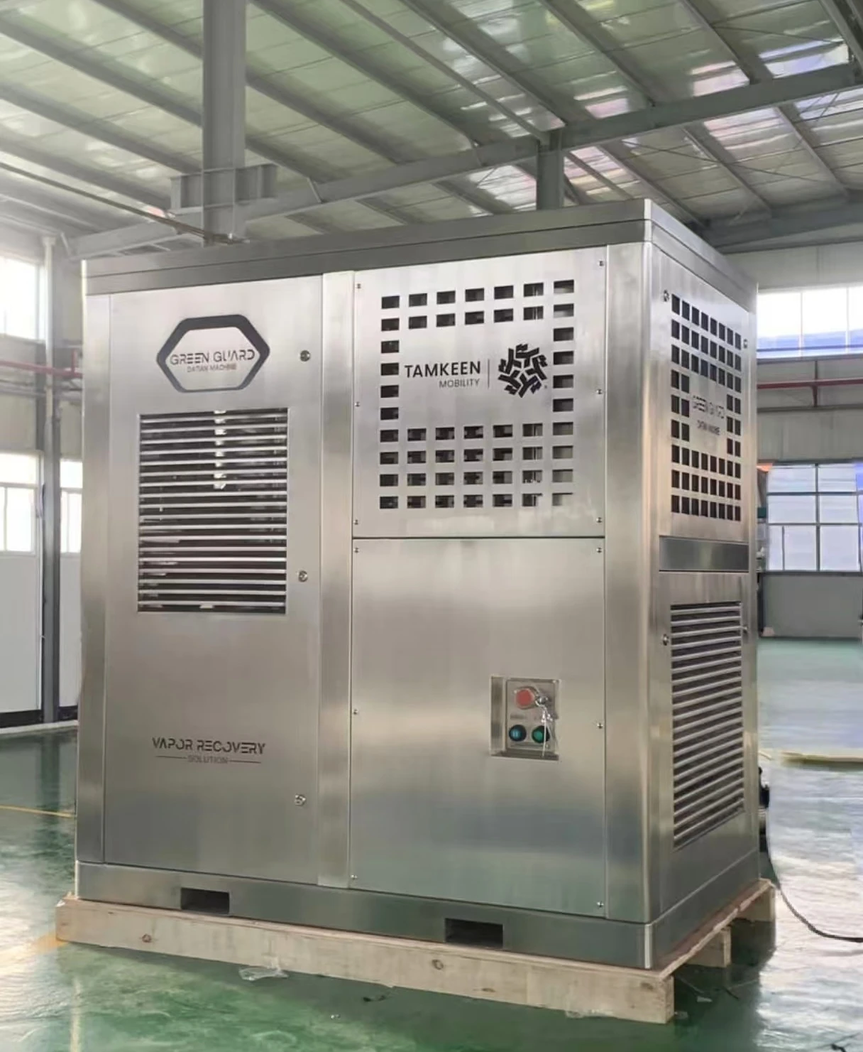
DT-100M
Membrane separation technology — no condensing equipment required.
Ideal for small gas stations — stable control of tank pressure and exhaust emission concentration.
Green Guard is Datian’s Stage III vapor-processing unit. It monitors underground storage tank pressure, condenses excess gasoline vapor through cooling and membrane separation, and returns it as liquid fuel — cutting VOC emissions by 95%+ while generating measurable savings. Three models cover the range — DT-100M, DT-VR26M1 and DT-VR26M2 — and the range is covered by EU-Type Examination Certificate IEP 26 ATEX 1835X.
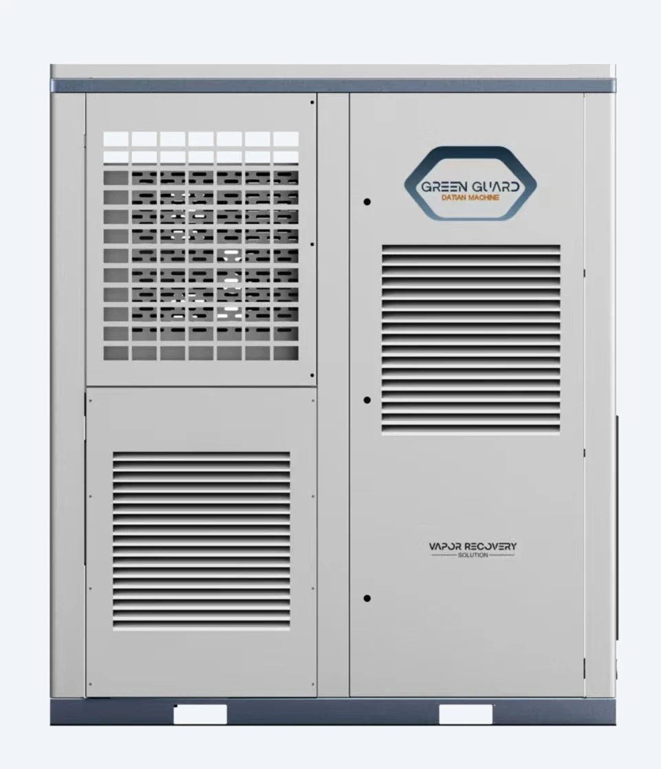
The latest Green Guard generation is built for stations that want compliance, lower emissions and a fast payback.
95%+ VOCs reduction: from 1,000–2,500 g/m³ down to <25 g/m³. Helps meet China, EU and Middle East environmental standards.
Typical fuel recovery 0.2–0.4%. Stations often see USD 3,000–20,000/year profit with low energy consumption.
24/7 autonomous operation, 4HP condenser module, optimized oil-gas separation and IoT remote control.
Role-based access, real-time safety alerts, tank-pressure trend tracking, VOCs emission analysis and 2+ years data storage.
Sensors measure underground storage tank pressure in real time. When pressure reaches the set threshold (4 to 5 mbar / 400 to 500 Pa), the unit starts automatically.
The vapor/air mixture is compressed, then cooled by an air-cooled heat exchanger to ambient temperature before entering the membrane modules. High-concentration vapor returns to the tank; cleaned air is discharged safely.
Recovered liquid drains back into the tank. The cloud dashboard logs every cycle, fuel savings and alarm event — accessible anywhere.
Choose the version based on your existing infrastructure.
Membrane separation technology — no condensing equipment required.
Ideal for small gas stations — stable control of tank pressure and exhaust emission concentration.
Pressure-auto or pressure & scheduled operation. Monitors tank pressure and starts according to regulation. Compact condensation unit with cloud interface. Ideal for stations with existing Stage I and Stage II systems.
Includes Stage I assist: during tanker unloading, vapor passes through the condensation unit to recover more fuel.
| Model | Stage I assist | Operation modes | Best for |
|---|---|---|---|
| DT-100M | No | Pressure-auto, Pressure & Scheduled | Moderate-temperature regions; pure membrane separation without condensing equipment |
| DT-VR26M1 | No | Pressure-auto, Pressure & Scheduled | Stations with existing Stage I & II systems that need tank pressure control, regulatory compliance and a cloud-connected condensation unit |
| DT-VR26M2 | Yes | Pressure-auto, Pressure & Scheduled + Stage I | Strongly recommended — stations with or without Stage I seeking maximum recovery |
Extracted from EU-Type Examination Certificate IEP 26 ATEX 1835X and the DT-VR26M1/M2 operation manual.
| Parameter | DT-100M | DT-VR26M1 | DT-VR26M2 | DT-VR26M2 Unloading Recovery |
|---|---|---|---|---|
| Operation mode | Pressure Auto | Pressure Auto | Pressure Auto | Unloading Recovery |
| Processing capacity | 4–8 m³/h | 6–12 m³/h | 6–12 m³/h | 18–22 m³/h |
| Vacuum pump pressure | -100 kPa to -80 kPa | -100 kPa to -80 kPa | -100 kPa to -80 kPa | — |
| Compressor pressure | ≤0.44 MPa | ≤0.44 MPa | ≤0.44 MPa | <0.2 MPa |
| Power | 3.5 kW | 6.5 kW | 7 kW | 7 kW |
| Voltage / Frequency | 220/380/415 VAC · 50/60 Hz | 220/380/415 VAC · 50/60 Hz | 220/380/415 VAC · 50/60 Hz | 220/380/415 VAC · 50/60 Hz |
| Ambient temperature | -20 °C to +50 °C | -20 °C to +50 °C | -20 °C to +50 °C | -20 °C to +50 °C |
IEP 26 ATEX 1835X — EU-Type Examination Certificate for use in potentially explosive atmospheres.
Vapour recovery is regulated in stages, and each stage is a different piece of equipment. Stage I covers bulk transfer into the underground tank, where vapour displaced by the incoming fuel is pushed back to the delivery tanker through a vapour return line. Stage 2 (usually written Stage II) covers the vehicle filling itself, where the nozzle draws displaced vapour back to the tank. Green Guard is a Stage III vapour recovery unit and sits downstream of both: it takes what Stage I vapor recovery and Stage 2 vapor recovery collected and returns it to the tank as liquid fuel instead of letting it vent.
Because it works on the vent side rather than at the nozzle, Green Guard is independent of the dispensing equipment you already run — no nozzle change, no balance line, and no requirement that the whole site be one brand. It is also why an ORVR compatible installation is not a problem: a vehicle with onboard refuelling vapour recovery captures its own vapour in a canister, so less comes back through the nozzle and more pressure stays in the tank. Managing that pressure is what the unit is built for. If your market specifies ORVR compatible operation, confirm the configuration with our engineers before ordering.
The latest Green Guard generation introduces four major improvements.
Modern enclosure aesthetics with improved access doors and serviceability.
Redesigned piping structure improves oil-gas separation efficiency.
Higher condensation capacity converts more oil vapor into liquid fuel.
Upgraded backend platform with intuitive interface and real-time monitoring.
Estimate recovered fuel and annual savings at your station.
Results are indicative only. Actual performance depends on temperature, pressure and fuel composition.
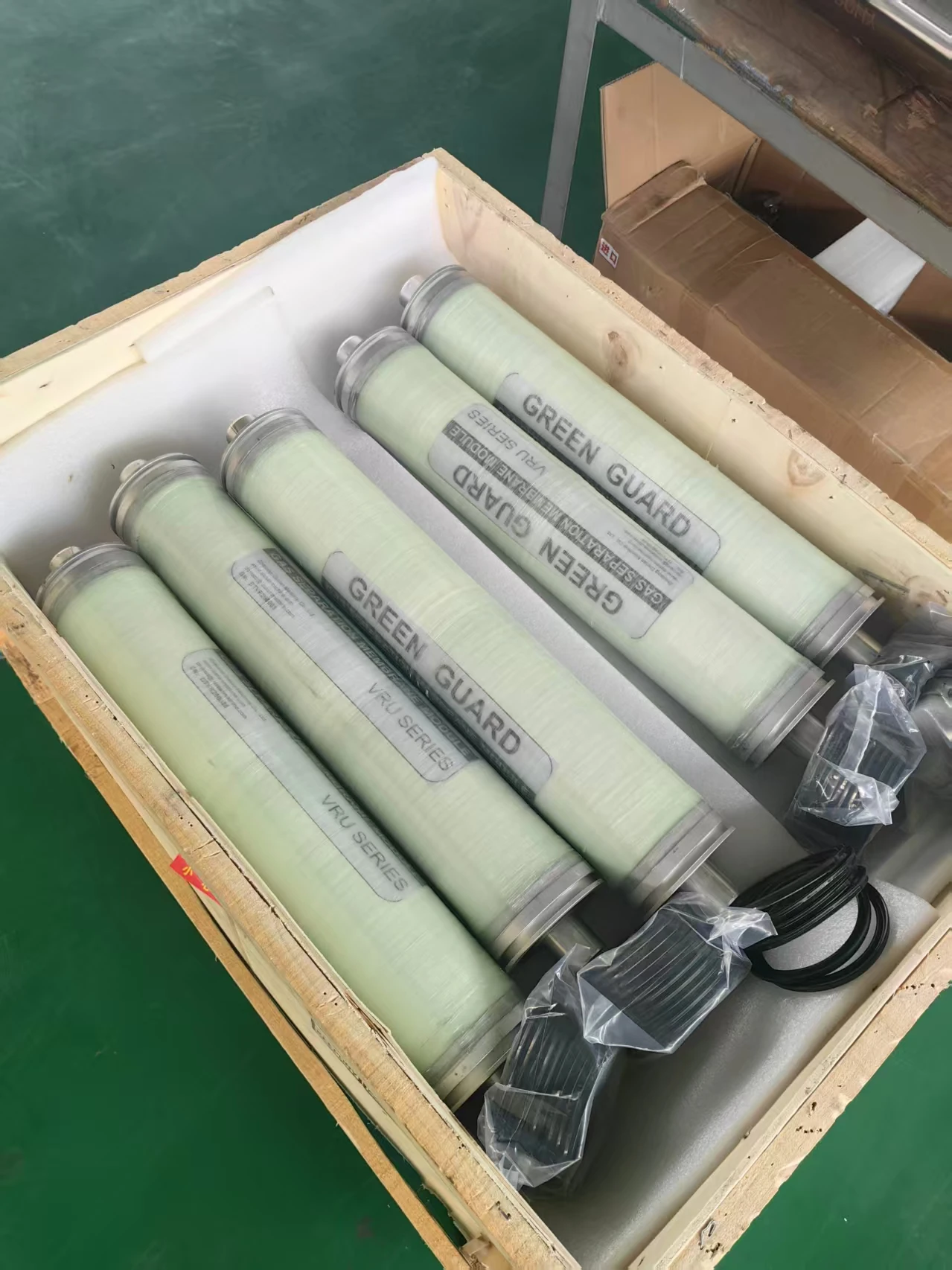
From our first-generation VRU to the latest Green Guard platform — factory photos, internal assemblies and membrane modules.
Throughput, recovery performance, peak-load behaviour, energy consumption and maintenance intervals — the questions forecourt operators and tender reviewers actually ask, answered by our engineering team.
Vapor leaving the storage tank during a delivery enters Green Guard at 150–160 L/min. Clean air leaves the unit at an adjustable 20–50 L/min, and the lower that discharge rate is set, the lower the VOC concentration carried out with it.
Tank pressure does not disturb the unit. The controller can be set so Green Guard keeps running for a further 30 minutes after a delivery, stopping automatically once the tank pressure has fallen back to 0 mbar, or on manual command.
On a typical station with three 30 m³ tanks, returning the tank to its normal pressure band takes three to four running cycles — about one hour.
Untreated vapor leaving a storage tank runs above 1,000 g/m³ of VOC. After Green Guard the measured concentration falls to about 20 g/m³, so more than 95% of the vapor is kept out of the air: part returns to the tank as liquid oil, part goes back through the vacuum pump.
Emission stays under 25 g/m³. A concentration sensor on the discharge pipe measures it in real time and feeds the control box in the office and the monitoring system. Recorded data can be downloaded, and the daily pressure trend is shown to the operator.
Peak business does not upset it. The compressor raises pressure to 380–440 kPa, and Green Guard works the tank pressure down step by step in cycles — typically 10 minutes running and 6 minutes standby, with the timing set to suit the site.
At a busy high-throughput station in China the tank pressure reached 2,500–3,000 Pa. Pressure-trend records taken at peak showed 1,000 Pa and 1,400 Pa, each brought down step by step by the cyclic operation.
Green Guard DT-VR26M2 is rated at 7 kW.
It does not run continuously. The unit starts when tank pressure rises to the set value — 4 to 5 mbar (400 to 500 Pa) — and stops again once pressure has fallen back to 0 mbar. One running cycle lasts 10 minutes, with the timing set to suit the site. How long it runs over a day depends on the tank pressure, the number of tanks and the temperature.
At a larger station the cumulative running time over a day may reach 6 to 8 hours — at 7 kW, roughly 42 to 56 kWh of electricity — and at a smaller site both the running time and the consumption are lower. Because the P/V valve and Green Guard’s pressure monitoring and running control work together, the vapor still cannot escape into the outside air.
The operating manual (P26, Operation Management and Maintenance) carries the full schedule, and the control box keeps a reminder record for it.
Component replacement intervals: the compressor is changed as a complete assembly at about 3 years, the membrane module at 3 to 5 years, the vacuum filter and the vacuum pump lube oil every 6 months, and the solenoid valve is replaced when it stops working.
Most of these parts are made in house by Datian Machine, so maintenance cost stays modest, and a spare-part price list is shared when cooperation starts.
Stage I vapor recovery captures the vapor pushed out of the storage tank while a tanker unloads. Stage II vapor recovery captures it at the nozzle while a vehicle is being filled and returns it to the tank through a second hose.
Stage III is the unit at the storage tank. Green Guard takes the vapor that Stage I and Stage II collected, condenses it and returns it to the tank as liquid fuel. A station can run Stage III on its own, or add it to an existing Stage I and Stage II installation.
Yes. Green Guard is installed at the storage tank rather than at the dispenser, so existing Stage II vapor recovery nozzles, hoses and breakaway valves stay in place and the forecourt keeps working.
For sites that still run standard dispensing equipment, Datian supplies the complete Stage II vapor recovery retrofit kit — the vacuum pumps DT-VR1, DT-VR2 or DT-NP80, coaxial hose, breakaway valves and ZVA-type vapor recovery nozzles — so the site is upgraded without replacing the dispensers.
Still have a question about your own station? Send us the tank size, the number of nozzles and your unloading rate — we will come back with the throughput figures for your site.
Talk to our engineering team and receive a technical and commercial proposal within 24–48 hours.
Get a Quote View Products