
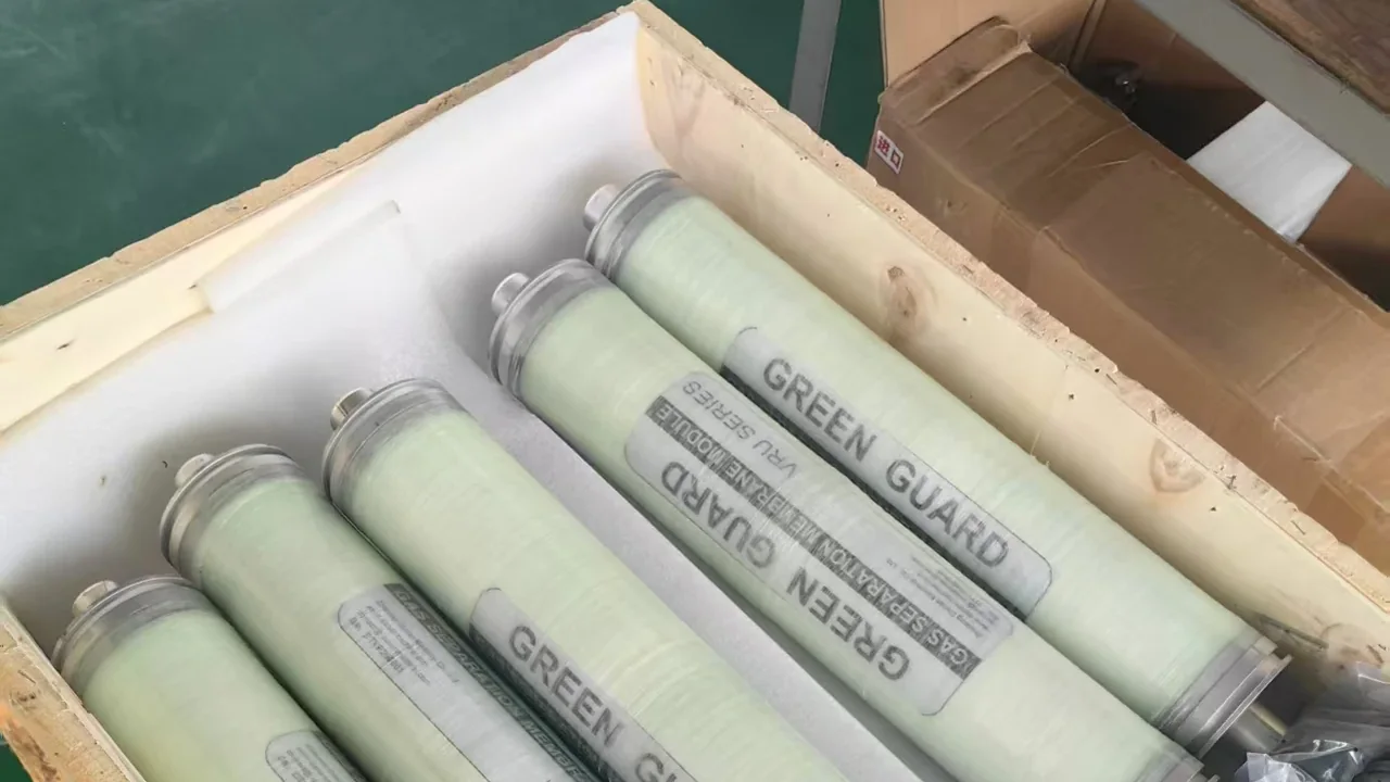
Vapor recovery equipment is usually sold on one efficiency figure and nothing else. This post publishes the instrument readings behind ours. A GreenGuard gas separation membrane was fed gasoline vapor at 700 g/m³, and the tail gas leaving it was measured with two detectors at five exhaust flow rates between 3.49 and 4.50 m³/h. The highest outlet concentration we could measure anywhere in that range was 5.1 g/m³.
How the test was set up
The test article was the gas separation membrane module that sits inside a GreenGuard vapor recovery unit. It is the last stage in the process: the vapor is compressed, then air-cooled back to ambient temperature (25 °C in this test) and fed straight into the membrane, which decides what is left to vent. There is no low-temperature condensation ahead of it. The module is a sealed cartridge, marked with the product family and the series.
Gasoline vapor was generated at a controlled concentration and fed to the membrane inlet at 700 g/m³. Everything reported below is the stream on the outlet side of the membrane, measured at the same time by three instruments:
- A rotary gas meter on the exhaust line, reading the tail-gas flow rate in m³/h.
- A low-range combustible gas detector, reading in % LEL. This instrument resolves concentrations in the single-digit region that a full-range device cannot show.
- A full-range combustible gas detector, calibrated 0–2000 g/m³, reading directly in grams per cubic meter.
Two detectors were run in parallel on purpose. The low-range instrument is the more sensitive of the two but reports in % LEL, which has to be converted before it says anything in g/m³. The full-range instrument reports in g/m³ directly but has no resolution at the bottom of its scale. Where the two agree, the outlet figure is solid; where they diverge, the gap is the conversion, not the membrane.
Measured results
This is the complete data set. The inlet was 700 g/m³ gasoline vapor at every point. The third column converts the low-range detector’s % LEL reading using the factor applied during the test, 100 % LEL of gasoline vapor being taken as about 38 g/m³, and is given for comparison only.
| Exhaust flow rate |
Low-range detector (% LEL) |
Low-range detector, as g/m³ (indicative) |
Full-range detector (g/m³) |
|---|---|---|---|
| 3.49 m³/h | 5 | ≈ 1.9 | 0.0 |
| 3.80 m³/h | 7 | ≈ 2.7 | 0.0 |
| 4.03 m³/h | 11 | ≈ 4.2 | 3.0 |
| 4.19 m³/h | 15 | ≈ 5.7 | 4.1 |
| 4.50 m³/h | 19 | ≈ 7.2 | 5.1 |
Inlet concentration 700 g/m³ throughout. Both outlet detectors and the gas meter were read simultaneously on the same stream.
The instrument readings at each flow rate
Each pair of photographs below comes from one run. The gas meter is on the left, the two detectors on the right, and all three were photographed at the same moment.
3.49 m³/h — 5 % LEL at the outlet
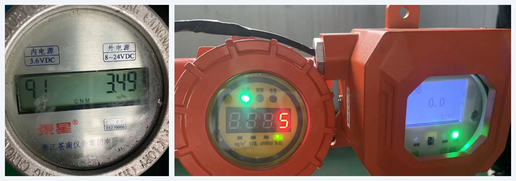
At the lowest flow rate tested the full-range detector read 0.0 g/m³, meaning the outlet was below what that instrument can resolve. The low-range detector, which is the more sensitive of the two, put the same stream at 5 % LEL.
3.80 m³/h — 7 % LEL at the outlet
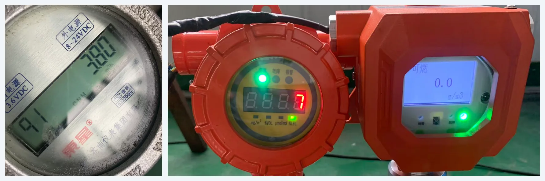
At 3.80 m³/h the picture is almost unchanged. The full-range detector still read 0.0 g/m³ and the low-range detector moved from 5 to 7 % LEL.
4.03 m³/h — 11 % LEL and 3.0 g/m³
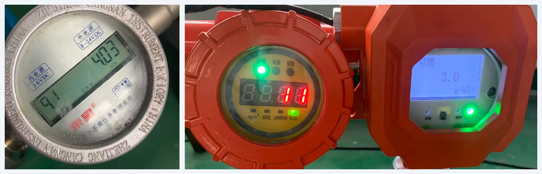
This is the point where the full-range detector starts to register: 3.0 g/m³ at 4.03 m³/h. The low-range detector reads 11 % LEL, which converts to roughly 4.2 g/m³ on the factor used here.
4.19 m³/h — 15 % LEL and 4.1 g/m³
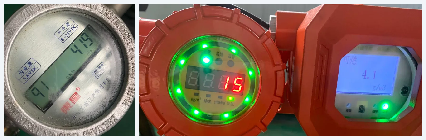
At 4.19 m³/h the full-range detector reads 4.1 g/m³ and the low-range detector 15 % LEL. The ring of indicator lamps on the low-range instrument is lit in this photograph, which is its own alarm display rather than a reading.
4.50 m³/h — 19 % LEL and 5.1 g/m³
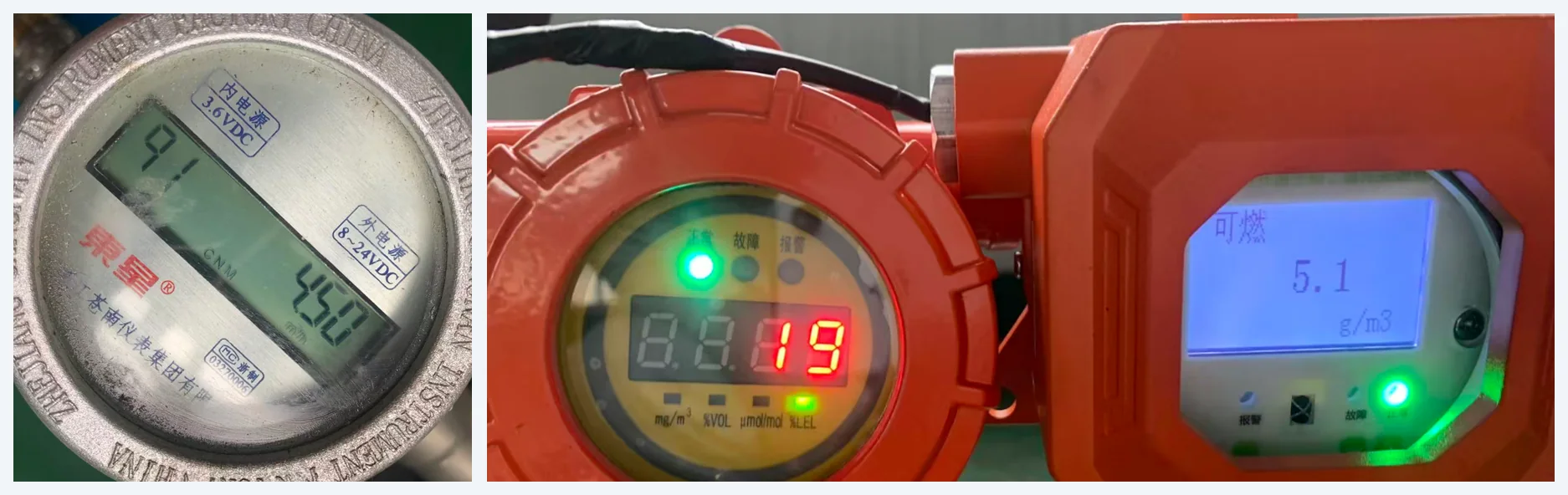
The highest flow rate tested, and the highest outlet concentration measured anywhere in the run: 5.1 g/m³ on the full-range detector, 19 % LEL on the low-range one.
What the numbers mean
Against an inlet of 700 g/m³, an outlet of 3.0 g/m³ is a reduction of 99.6 %. At 5.1 g/m³, the worst point in the range, it is still 99.3 %. At the two lowest flow rates the full-range instrument read zero, so the outlet was below the 0.1 g/m³ step that instrument displays. Across the whole band, measured on the full-range detector, the membrane removed better than 99 % of the hydrocarbon it was fed.
Three things in the data are worth pointing out.
The outlet concentration rises with exhaust flow rate. 0.0 g/m³ at 3.49 m³/h becomes 5.1 g/m³ at 4.50 m³/h. That is the expected direction: a higher exhaust flow means a shorter contact time inside the module, so a slightly larger share of the hydrocarbon travels through with the vent gas. The rise is gradual and the absolute figures stay low, which is what a correctly sized membrane element should do.
4.50 m³/h is a large exhaust flow. The point of running the test that far up is that a forecourt VRU sees its highest exhaust flows during fuel deliveries, when several tanks are being filled at once. Even at that flow the outlet stayed at 5.1 g/m³.
The two detectors do not report the same number. At 4.03 m³/h the low-range instrument reads 11 % LEL, which converts to about 4.2 g/m³, while the full-range instrument reads 3.0 g/m³. The gap is the conversion factor rather than a disagreement about the stream: converting % LEL to g/m³ depends on the assumed composition of gasoline vapor, and real forecourt vapor is a mixture rather than a single compound. What both instruments agree on is the order of magnitude — the outlet sits in the low single digits of g/m³, more than two orders of magnitude below the inlet.
Frequently asked questions
Gasoline vapor at 700 g/m³ at the membrane inlet, held at that concentration for every one of the five flow rates. Gasoline was chosen because it is the vapor a forecourt VRU actually handles, and 700 g/m³ is a heavily loaded stream rather than a convenient laboratory value.
The gas meter read 3.49, 3.80, 4.03, 4.19 and 4.50 m³/h across the five runs. The top of that range is a large exhaust flow for a vapor recovery unit: it corresponds to a station recovering vapor at the rate a busy forecourt produces it during a delivery, not at idle. Running the test to 4.50 m³/h is what shows how much margin the membrane has.
With two combustible gas detectors on the same outlet stream, read at the same time. One is a low-range instrument that reports in % LEL and resolves small concentrations; the other is a full-range instrument calibrated 0–2000 g/m³ that reports directly in grams per cubic meter. The exhaust flow rate was read from a rotary gas meter on the same line. Using two instruments with different measuring principles is deliberate: a single detector can be misread or miscalibrated, two independent ones agreeing cannot.
Measured on the full-range detector against the 700 g/m³ inlet, the reduction was 99.6 % at 4.03 m³/h and 99.3 % at 4.50 m³/h. At 3.49 and 3.80 m³/h the outlet was below that instrument’s resolution, so the reduction there was greater still. Over the tested band the membrane removed better than 99 % of the hydrocarbon entering it.
They are bench readings from a factory test with a controlled inlet, not a site emission report. A station-specific figure depends on tank volume, throughput, product and ambient temperature, and has to be measured on site. What these readings establish is the capability of the separation membrane itself, and they are the numbers we are prepared to be held to when a membrane module leaves the factory.
Where to go next
The membrane module in this test is part of the GreenGuard vapor recovery family. Full specifications and model selection are on the GreenGuard specification page, and throughput, recovery performance, power consumption and maintenance intervals are answered in the GreenGuard FAQ. Installation photographs are in the GreenGuard gallery.
For the wider picture, what makes a GreenGuard VRU different explains why we publish emission data at all, and condensed liquid in vapor recovery looks at how to measure the fuel a vapor recovery unit actually saves. Retrofitting an existing forecourt rather than specifying new equipment? The Stage II vapor recovery parts range covers the balance-line hardware, including vapor recovery pumps.