
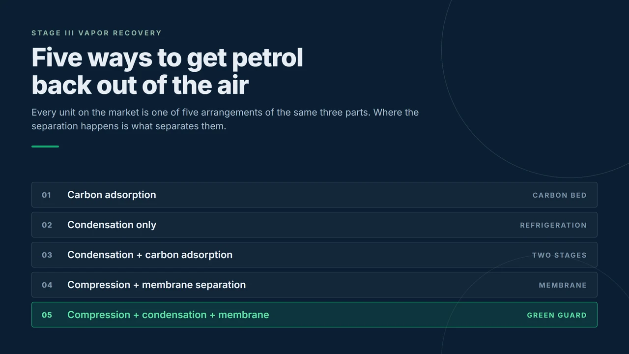
Every Stage III vapor recovery unit sold for a service station is an arrangement of three parts: a surface that gets cold, a membrane that separates, or a bed of carbon that captures. Arrange those three in every commercially useful order and you get five architectures. This is the map, drawn before any brand is named.
Three ways to take hydrocarbon out of air
Vapor pushed out of a storage tank is a mixture. The hydrocarbon in it is worth recovering; the air in it has to go somewhere. Every Stage III unit therefore does the same job, which is to find the hydrocarbon, keep it, and let the air out clean. Only three separation mechanisms are in commercial use.
- Cold. Cool the mixture below the hydrocarbon dew point and it condenses into liquid that can be pumped back to the tank. One stage is never enough; the units on the market step down through intermediate temperatures, typically around +3 °C, then −25 °C, then −45 °C.
- A membrane. Pressurise the mixture and pass it across a polymer film. Hydrocarbon molecules dissolve into the film and travel through it faster than nitrogen and oxygen do, so one side becomes a hydrocarbon-rich permeate and the other a clean retentate.
- Carbon. Pass the mixture through a bed of activated carbon, which holds the hydrocarbon while air passes. When the bed saturates, it has to be regenerated under vacuum, and the desorbed vapor is returned to the tank or taken to an absorber.
The five arrangements that follow are not five grades of the same machine. Each is a different answer to one question: where do you want the separation to happen, and what will you pay for it in energy, maintenance and floor space.
Path 1: carbon adsorption
Vapor passes through an activated carbon bed; air goes out, hydrocarbon stays behind. When the bed is saturated it is regenerated under vacuum and the concentrated vapor is returned to the tank. Recovery reaches 95 to 97% in a single bed and higher in combination, and deep adsorption can hold the outlet below 10 g/m³. It also has the lowest capital cost of the five, which is why it was the default first choice for a decade.
Two things ended that. Adsorption releases heat, and a saturated bed with uneven heat removal develops hot spots, which is a fire risk rather than an efficiency question. And spent carbon is a hazardous waste stream: the bed is changed on a cycle that in practice runs one to three months, and the used media has to go through a licensed disposal route, whether or not the site has a problem. In China, the pure carbon adsorption units installed ten years ago have effectively disappeared from service stations, and it was not efficiency that retired them: it was the maintenance cost, the frequency of it, and the secondary pollution that comes from handling and disposing of the spent media.
Path 2: condensation only
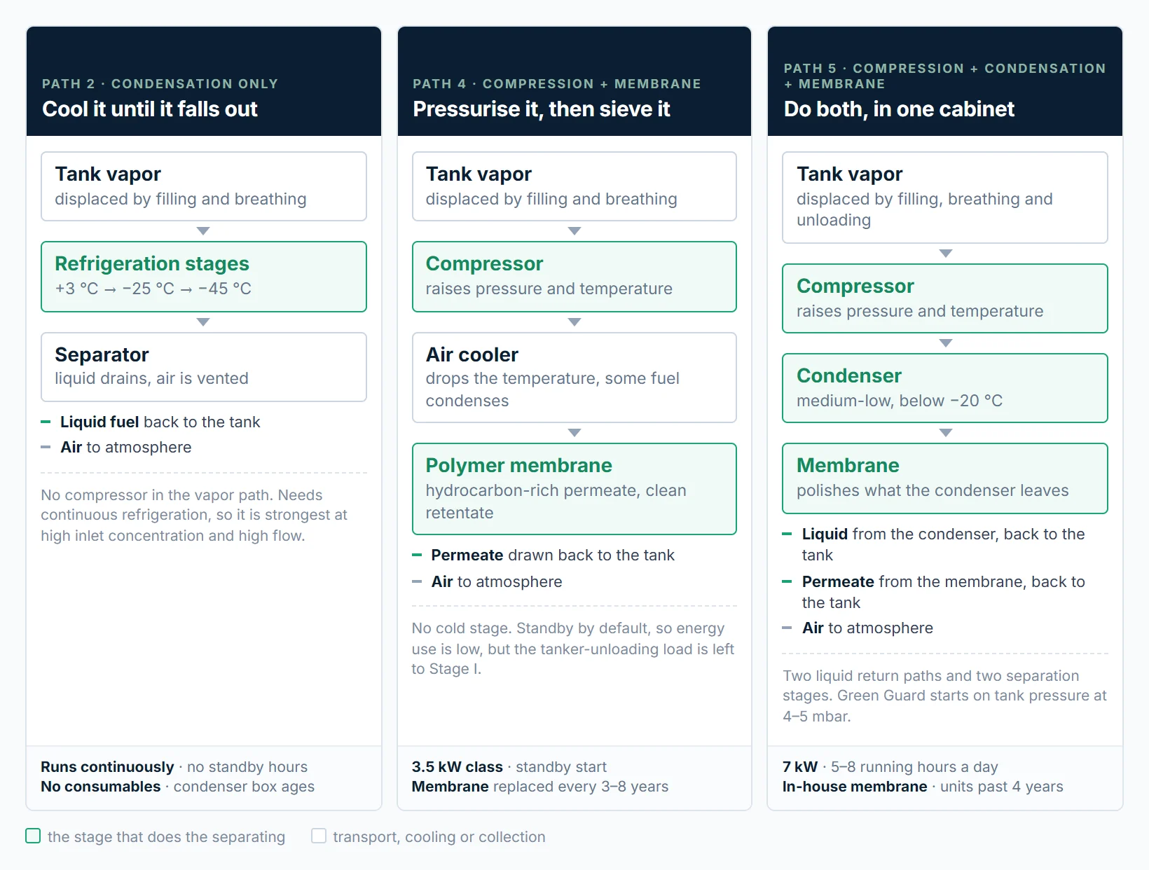
Cool the vapor until the fuel drops out, collect it, vent the air. No consumables, no bed to regenerate, and the recovered liquid is visible on the daily tank gauge. Single-stage condensation reaches 85 to 95%; three stages get past 98%, but the third stage is where the electricity goes. It is also the most expensive of the three to run, because the refrigeration plant has to run continuously: the cold surface has to be cold before the vapor arrives, so there is no standby hour to save.
That combination decides where the architecture fits. Condensation only closes its economics where the inlet concentration is high and the flow is large, which is a depot or a loading rack, not a service station that runs a few hundred hours a year. At low inlet concentration the same unit has to work harder to hold a tight outlet limit and recovers less while doing it.
Path 3: condensation plus carbon adsorption
Condense first, then polish the off-gas through carbon. The pre-cooling step protects the bed from hot spots and does most of the work, so the carbon only has to catch what is left, and the combination reaches roughly 95 to 98% with measured outlets typically between 3 and 11.8 g/m³. It was the mainstream Chinese station solution for about a decade and is still common in compliance retrofits.
The cost is structural: two subsystems, two maintenance schedules, and a hazardous waste stream that does not exist on the other four paths. Where a permit authority has tightened the rules on spent carbon, this arrangement is being pushed out by the two that follow.
Path 4: compression plus membrane separation
A compressor raises the pressure, an air cooler knocks the temperature back down and condenses part of the fuel, and the membrane separates what is left. A vacuum pump draws the hydrocarbon-rich permeate back to the tank, and clean retentate goes to atmosphere. Single stage efficiency runs 90 to 96%, and two membrane stages in series get past 97%.
The architecture's advantage is that it can stand still. With no cold surface to keep cold, the unit waits until tank pressure crosses a setpoint, runs, and stops. That is the whole energy advantage: a 3.5 kW membrane unit running 5 to 8 hours a day bills a fraction of what a condensing unit bills for holding temperature around the clock. The trade-off is the opposite of path 2: there is no cold stage to absorb a large vapor load, so during tanker unloading the 18 to 22 m³/h spike is normally left to Stage I, and in a hot climate the air cooler has less margin to work with.
Path 5: compression, condensation and membrane
Put all three in one cabinet. The compressor raises pressure, a condenser at a medium-low temperature, below −20 °C, liquefies the bulk of the hydrocarbon, and the membrane polishes the tail. Two liquid return paths and two separation stages in series. Because the condenser works below −20 °C rather than at −45 °C, the refrigeration load is far below path 2, and because the membrane polishes the tail, the outlet concentration does not depend on holding a deep cold stage through a hot afternoon.
The unit is standby by default and starts on tank pressure, so its running hours are the lowest of the five. The price is the most complex architecture of the set, the highest capital cost, and more components that can fail. Published claims for this class run from 95 to 99% depending on inlet concentration, and any figure at the top of that range should arrive with a third-party test report attached.
The five, side by side
| Path | Separation | Recovery | Energy | Consumables | Unloading vapor |
|---|---|---|---|---|---|
| 1 Carbon adsorption | Carbon bed, vacuum regenerated | 95–97%, 98%+ combined | Blower and vacuum pump, on demand | Carbon, 1–3 months, hazardous waste | No |
| 2 Condensation only | Multi-stage refrigeration | 85–95%, 98%+ at three stages | Refrigeration runs continuously | None; condenser box ages | Yes |
| 3 Condensation + carbon | Condense, then adsorb | 95–98% | Between paths 1 and 2 | Carbon, 1–3 months, hazardous waste | Yes |
| 4 Compression + membrane | Polymer membrane | 90–96%, 97%+ in series | 3.5 kW class, standby start | Membrane, 3–8 years | No |
| 5 Compression + condensation + membrane | Condense, then membrane polish | 95–99% claimed | 7 kW, 5–8 hours a day | In-house membrane | Yes, with Stage I assist |
Where the field has settled
Read the table down the last two columns and the field sorts itself. Carbon-bearing paths are losing ground wherever spent carbon has to be declared and shipped, because that is a permanent operating obligation attached to a unit that was bought on price. Condensation only remains a depot technology: at a loading rack with high concentration and long duty it is efficient, and at a service station it is an expensive refrigerator.
What is left is the argument between paths 4 and 5, and it is not an argument about recovery percentage. Both can hold a tight outlet. It is an argument about the unloading hour and about who services what. Path 4 leaves the 18 to 22 m³/h unloading spike to Stage I and asks the site to replace a membrane module every few years. Path 5 takes the spike through the condenser and gives up simplicity and capital cost to do it.
Which of the two a station should buy is decided by four numbers, and none of them is the efficiency figure on the brochure. They are covered in how to specify a Stage III unit. The three-way comparison between named architectures is in condensation, membrane or hybrid, and the history of how this company moved through paths 1, 2, 3 and 5 is in the evolution of Datian vapor recovery.
Which of the five we build
Green Guard is a path 5 machine, and one path 4 machine, depending on the model. The DT-100M is membrane separation without condensing equipment, 4 to 8 m³/h at 3.5 kW, for stations in moderate climates that do not want refrigeration on site. The DT-VR26M1 and DT-VR26M2 are the hybrid: 6 to 12 m³/h at 6.5 and 7 kW, with the M2 adding Stage I assist so the tanker-unloading vapor passes through the condenser at 18 to 22 m³/h instead of being routed back to the truck. All three carry the same EU-type examination certificate, IEP 26 ATEX 1835X, for zone 0 and zone 1 installation.
The models, drawings and certificate are on the Green Guard page. If you are choosing between paths rather than models, send the station throughput, the tank count and the outlet limit your permit states, and we will tell you which of the five we would build for it, including when the answer is not ours.
Common questions
Path 4 or path 5. A station does not run continuously, so the two architectures that stand on standby and start on tank pressure cost less to own than the three that do not. Between them the decision is the unloading hour: if the site wants the tanker-unloading vapor recovered rather than returned to the truck, that is path 5 with Stage I assist. Carbon adsorption is cheaper to buy and more expensive to keep, because the bed has to be replaced and disposed of on a fixed cycle.
Because the cold surface has to stay cold whether or not vapor is arriving. A condensing unit at −45 °C runs its refrigeration circuit continuously, so there is no standby hour to save. A membrane unit has no cold surface, so it sits idle until tank pressure crosses a setpoint and stops again when the pressure falls. The gap is duty cycle, not compressor efficiency, which is why we quote power and running hours rather than a figure per cubic metre.
It is allowed in most jurisdictions, and it still reaches a low outlet concentration. What changed is the operating cost: activated carbon is replaced every one to three months, or sooner if the bed saturates, whether or not it looks spent, and the used carbon is classified as hazardous waste, so it needs a licensed disposal route and a record. Where a site cannot maintain that paperwork, the arrangement becomes a liability rather than a saving.
Datian has been building vapor recovery equipment since 2015 and has shipped all four of the paths we still support. If you have a permit figure to hit and a station to fit, send us the numbers and we will answer with the architecture and the model, not with a brochure.